Free Beam Calculator
Calculate bending moment, shear force, deflection & reaction forces for cantilever & simply supported beam.
Second moment of area: 473.0cm4
Youngs Modulus: 210.0GPa
Support conditions are unsatisfactory, add another support.
Min Deflection: -
How the beam analysis is solved
The beam is solved using the direct stiffness method. Each span is discretised into elements with two degrees of freedom per node, assembled into a global stiffness matrix, and solved for nodal displacements and rotations under the applied load vector. Bending moment, shear force and deflection are then recovered element-by-element.
What's this calculator used for?
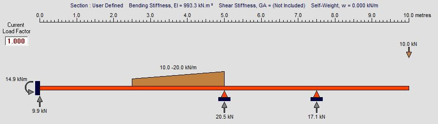
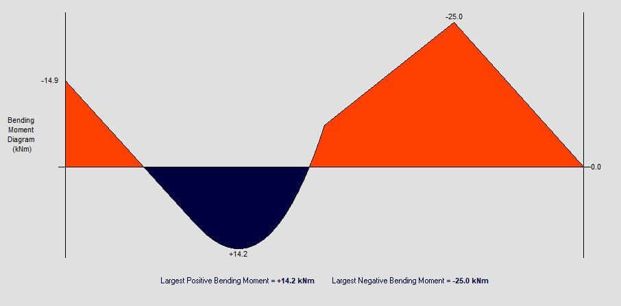
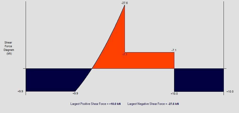
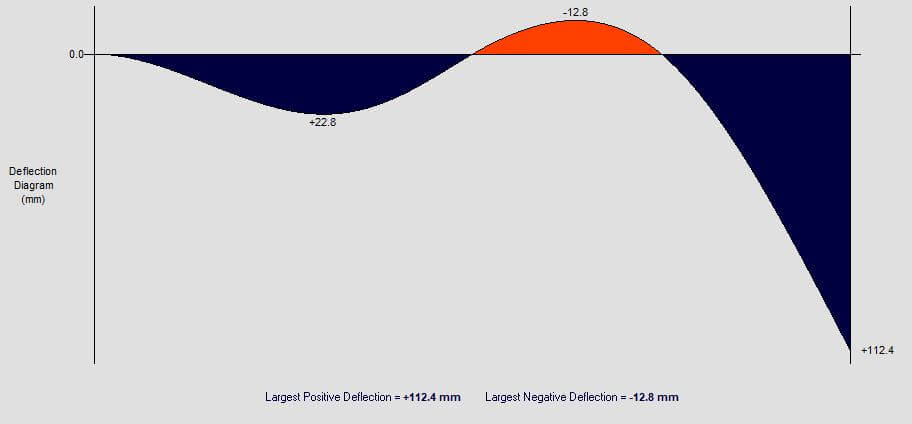
Free online beam calculator to draw bending moment diagrams, shear force diagrams, calculate reaction forces and measure deflection for an indeterminate beam span. This calculator can be used for structural analysis and beam analysis. Maximum bending moment can be calculated along with shear forces, reaction forces and deflection using steel section properties. Specify beam geometry and point loads or distributed loads to get started analysing the beam.
- Normal stress: Generated from forces act along the length of the beam in compression or tension.
- Shear stress: Generated from forces act parallel to the direction of the load.
- Point loads: This is a force applied to a single point on the beam.
- Distributed loads: This force is distributed over a certain length and acts as a form of pressure.
- Concentrated moment: This is a pure moment acting on a beam at a given position.
- Pinned support: Restrain the beam in both horizontal and vertical directions without providing any restraint against rotation.
- Roller support: Support provided to the beam in only a single direction and no restraint against bending or rotation.
- Fixed support: These supports provide restraint to the beam in all directions and restrain against rotation.
Free body force diagram
- Σ Vertical forces applied = 0kN
- Σ Horizontal forces applied = 0kN
- Σ Moments applied = 0kNm
- Statically determinate: Where the number of equations is equal to the number of unknowns and the calculations can be solved using closed form hand calculations.
- Statically indeterminate: Where the number of unknowns exceeds the number of equations and more advanced methods such as Moment Resistribution Theory need to be used.
Learn to build tools for yourself
Our Python for Civil Engineering certification walks you through publishing four tools like this one.
Enroll nowThis calculator is open source
Contribute to IndeterminateBeam on GitHub. Special credits: Jesse Bonanno.
Interested in learning more about automation?
Enroll on our training certifications and learn how to code, build AI applications with no-code tools and automate tasks.
Learn moreUpdate beam length
Edit beam section