Free Reinforced Concrete Calculator

Analyse an RC beam or column design in accordance with Eurocode 2 with this rebar calculator.

Free, no sign-up Eurocode & AISC Open source PDF report
Concrete section profile
Concrete Strength fck MPa
Enter strength more than 0 & less than 60MPa.
Section width mm
Enter width more than 0 & less than 3000mm.
Section depth mm
Enter depth more than 0 & less than 3000mm.
Applied loading
Bending Med,y kNm
Enter moment greater than 0.
Axial Ned kN
Only axial compression is considered.
Bottom reinforcement
No. bars
Bar diameter mm
Cover (to bottom) mm
Enter cover greater than 0 & less than depth/2
Advanced settings:
Shear Ved kN
Enter shear greater than 0.
Specify the top reinforcement
No. bars
Bar diameter mm
Cover (to top) mm
Enter cover greater than 0 & less than depth/2
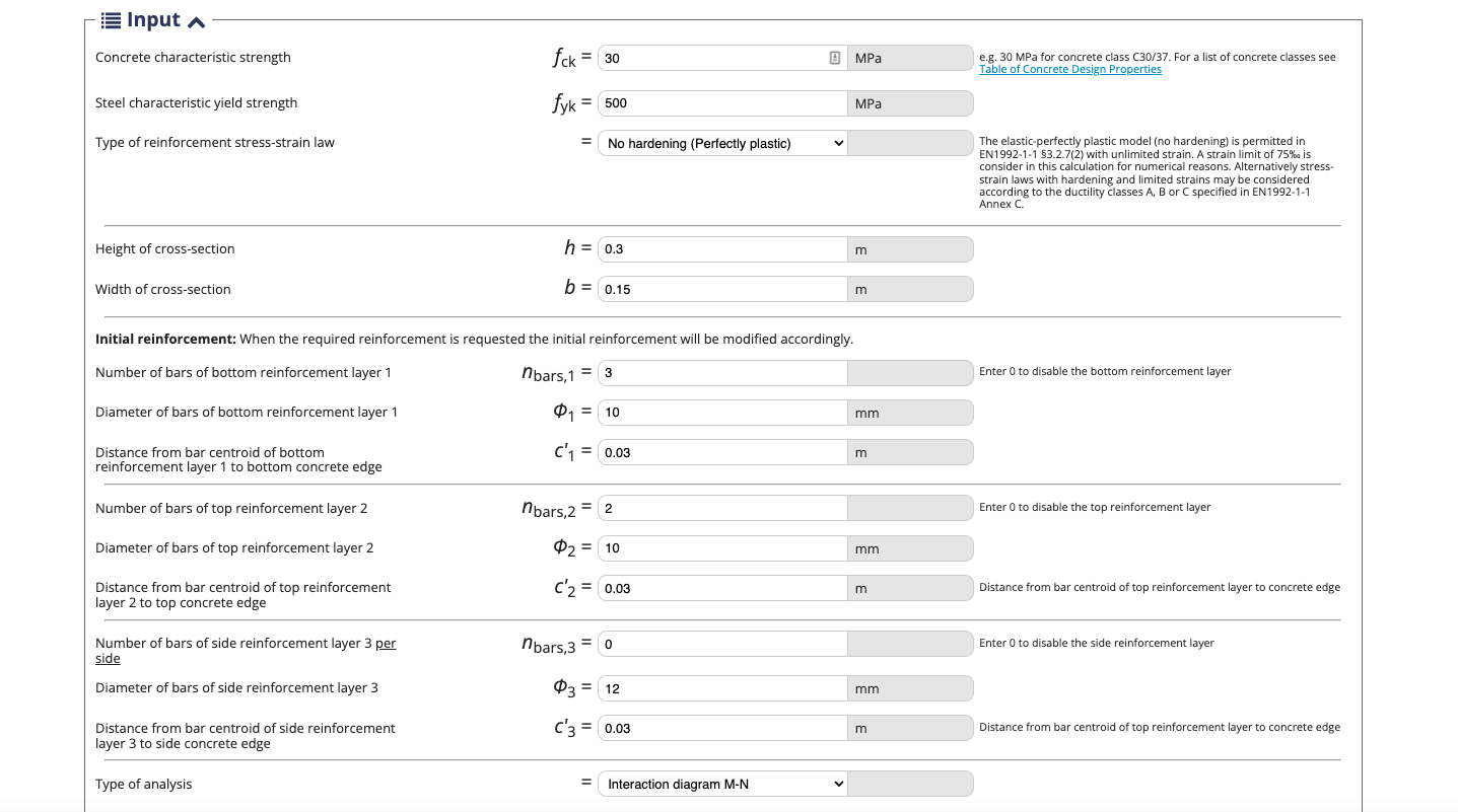
4. Reinforcement properties:
Steel strength   fyk MPa
Enter strength greater than 0 & less than 700MPa
Cover to edges   mm
Enter cover greater than 0 & less than width/2
Reinforcement spacing
Top bar spacing: mm
Bottom bar spacing: mm
Minimum allowable top bar spacing: mm
Minimum allowable bottom bar spacing: mm

Reinforcement area
Reinforcement area top: mm2
Reinforcement area bottom: mm2
Total reinforcement: mm2 (%)
Min reinforcement limit: mm2 (%)
Max reinforcement limit: mm2 (%)
Result
ULS
%
SLS
%
Warnings:
❌ Top bars seem too close.
❌ Bottom bars seem too close.
❌ Cover to the top seems too little, try >30mm.
❌ Cover to the bottom seems too little, try >30mm.
❌ Cover to the sides seems too little, try >30mm.
❌ Check your reinforcement area is within max & min limits.
d
mm
x
mm
es1 es2 σ's1
N/mm2
σ's2
N/mm2
M1
Nmm
M2
Nmm
M3
Nmm
M
kNm
N
kNm

Calculation Results

Loading...
Ultimate limit state
ULS result
M-N utilisation %
Shear analysis
Serviceability limit state
SLS result
Neutral Axis Depth mm
Assumed crack limit 0.3mm
Short term crack width mm
Long term crack width mm
Method & theory

How the concrete section is checked

The section is checked against Eurocode 2: for each neutral-axis position the axial and bending resistance is calculated, tracing out a capacity envelope, then shear link area and short/long-term crack widths are checked against the applied ultimate and serviceability design forces.

Watch how it works
What's this calculator used for?

This free calculator can be used by Civil Engineers to design reinforced concrete. This tool can be used to calculate reinforcement and rebar areas and calculate bar spacings are correct against the European regulations (Eurocode 2). Calculate the neutral axis of a reinforced concrete beams and used it to determine the tension and compression stresses resulting from the bending moment. Design the shear reinforcement and check that concrete short term and long term crack widths comply with servicibility limit state.

Common questions

Concrete’s strength, cost and availability has made it the most widely used construction materials of the 21st century. Concrete is made from cement mixed with water. Often stone aggregate and chemical admixtures are added to the mix to improve the material structural performance and workability. The most common mix of cement, aggregates and water used is in the ratio 1:2:4.

Concrete is weak in tension and shear. Steel reinforcement forms a bond with concrete and provides concrete with tensile strength, prevent dangerous brittle failure of the material. Brittle failure is dangerous in unreinforced concrete as occurs suddenly and provides no warning that the material is about to fail.

When a beam flexes one face of the beam experiences tensile stress and the other experiences compressive stress. A neutral axis forms, along which line the stress is zero. The neutral axis position depends on the position and specification of any steel reinforcement and the nature of the applied load.

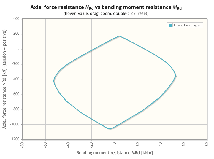
Each neutral axis position within the concrete section will have a resulting axial and bending resistance. Plotting the axial resistance against the bending resistance for each neutral axis position creates an envelope which represents the capacity of the concrete section.

Shear links are used to resist shear force applied to concrete. The concrete strut capacity equation is used to determine the area of shear links required to provide the necessary shear link resistance.

  • A minimum reinforcement area of 0.24% of the concrete section area should be provided as a typical value.
  • In order to provide crack control and satisfy SLS requirements a minimum area of reinforcement must be provided to concrete. The amount can be estimated from an equilibrium equation between the tensile force in concrete before cracking and the tensile force in reinforcement at yielding.
  • Minimum reinforced concrete steel area can be calculated with the equation
  • As,mín·σs = kc · k · fct,eff · Act
  • Where As,min is equivalent to the minimum area required within the tensile zone.
  • Act is the area of concrete within the tensile zone.
  • σs is the stress in the steel after crack formation, this can be taken as the yield strength of the steel
  • fct,eff is the tensile strength of the concrete
  • k is the coefficient which allows for the effect of non-uniform self-equilibrating stresses, which lead to a reduction of restraint forces
  • = 1,0 for webs with h ≤ 300 mm or flanges with widths less than 300 mm
  • = 0,65 for webs with h ≥ 800 mm or flanges with widths greater than 800 mm
  • kc is a coefficient which takes account of the stress distribution within the section immediately prior to cracking and of the change of the lever arm:
  • For pure tension kc can be taken as = 1,0, this can also be used for all cases as a conservative value.

A maximum of between 1% and 2% of the concrete area should be provided as reinforcement

  • The minimum spacing between bars should be greater than the bar size, the maximum aggregate size + 5mm, or 20mm according to Eurocode 2 (EC2)
  • The minimum horizontal spacing between bars should be greater than the bar size or the maximum aggregate size + 5mm. The minimum vertical spacing between bars should be greater than the bar size or 2/3 of the maximum aggregate size according to BS8110
The compressive stress in the concrete shall be limited in order to avoid longitudinal cracks, micro-cracks or high levels of creep, where they could result in unacceptable effects on the function of the structure.
Longitudinal cracks may occur if the stress level under the characteristic combination of loads exceeds a critical value. Such cracking may lead to a reduction of durability. In the absence of other measures, such as an increase in the cover to reinforcement in the compressive zone or confinement by transverse reinforcement, it may be appropriate to limit the compressive stress to a lower value for concrete exposed to harsh exposure conditions.

Concrete column capacity charts can be used to calculate the reinforcement area requirements from height, width and the applied axial force and bending.
Calculation validation

Certification

Learn to build tools for yourself

Our Python for Civil Engineering certification walks you through publishing four tools like this one.

Enroll now
This calculator is open source

Contribute to Concrete-Properties on GitHub. Special credits: Robbie van Leeuwen.

View on GitHub

Interested in learning more about automation?

Enroll on our training certifications and learn how to code, build AI applications with no-code tools and automate tasks.

Learn more