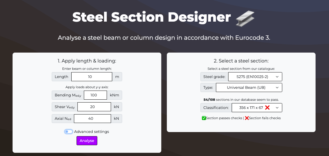
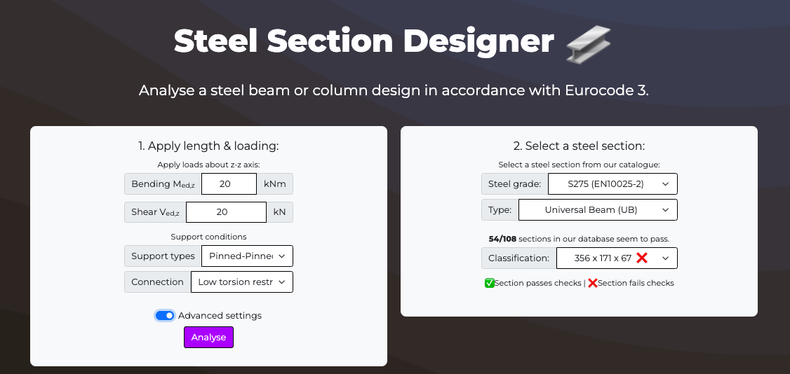
Free Steel Section Designer
Analyse a steel beam or column in accordance with Eurocode 3.
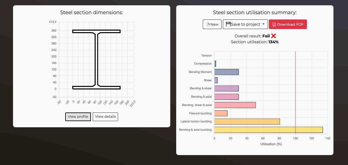
Result
Utilisation
%
Section Depth
mm
Section Width
mm
Web thickness
mm
Flange thickness
mm
Total Area
cm2
Root
mm
Y-Y Axis:
1st moment of area
cm4
2nd moment of area
cm4
Wpl,y
cm3
Wel,y
cm3
Z-Z Axis:
1st moment of area
cm4
2nd moment of area
cm4
Wpl,z
cm3
Wel,z
cm3
Steel analysis summary
Universal
Beams
Universal
Columns
European
Beams
European
Columns
American
Beams
SHS
(Square)
RHS
(Rectangle)
CHS
(Circle)
Loading...
Apply loads about z-z axis:
Bending Med,z
kNm
Enter value greater than 0.
Shear Ved,z
kN
Enter value greater than 0.
Support conditions
Support types
Connection
results
The classification of the cross-section parts (flanges and web) of steel material is specified in EN1993-1-1 Table 5.2. In this calculation cross-section classification is carried out for the case of predominant axial force NEd and bending moment My,Ed about the major axis y-y. For this case the web is classified for the combination of bending and compression and the compressive flange is classified for pure compression. The class of the compression part depends on its width c to thickness t ratio, adjusted by the factor ε = 1.000. The classification of the total cross-section is determined by the class of its most unfavorable compression part, web or flange.
Flange classification:
- For the compression flange: c / t = (b / 2 - tw / 2 - r) / tf =
- Flange classification: Class
The classification of the cross-section parts is specified in EN1993-1-1 Table 5.2
Web classification:
- For the Web: c / t = (h - 2⋅tf - 2⋅r) / tw See table 5.2 for element subject to bending and shear (α = ) c / t =
- Web classification: Class
Section classification: Class
The shear buckling resistance of the web is verified in accordance with EN1993-1-1 §6.2.6(6):
- Shear buckling resistance without additional measures is proven when: hw/tw ≤ 72 ⋅ ε / η
- 72 ⋅ ε / η =
- hw/tw =
Result:
The critical cross-section is verified for tensile axial force in accordance with EN1993-1-1 §6.2.3:
- NEd / Nt,Rd ≤ 1.0
- Where NEd = kN is the design tensile axial force. The tension resistance Nt,Rd is estimated as the plastic tension resistance Npl,Rd on the basis of the gross cross-section area A and the steel yield stress fy.
- Npl,Rd = kN
Result:
Utilisation:
According to EN1993-1-1 §6.2.3(2)b) for the case where holes for fasteners or other openings are present the tension verification must also be performed on the basis of the net cross-section area Anet and the steel ultimate stress fu>: Nu,Rd = 0.9 ⋅ Anet ⋅ fu / γM2
The critical cross-section is verified for compressive axial force in accordance with EN1993-1-1 §6.2.4:
- NEd / Nc,Rd ≤ 1.0
- Where NEd = kN is the design compressive axial force. For the case of class 1, 2, or 3 cross-section the compression resistance Nc,Rd is estimated as:
- Nc,Rd = kN
Result:
Utilisation:
Verification is sufficient for steel members without holes or with fastener holes filled with fasteners with the exception of oversize and slotted holes.
The critical cross-section is verified for bending moment in accordance with EN1993-1-1 §6.2.5:
MEd / Mc,Rd ≤ 1.0
- For class 1 or 2 cross-sections the design resistance Mc,Rd for bending about one principal axis is estimated as the corresponding plastic bending resistance Mpl,Rd on the basis of the corresponding plastic section modulus Wpl:
- For the major axis y-y: Mc,y,Rd = Wpl,y ⋅ fy / γM0 = kNm
- For the minor axis z-z: Mc,z,Rd = Wpl,z ⋅ fy / γM0 = kNm
- For bending about the major axis y-y utilisation:
- For bending about the minor axis z-z utilisation:
Bending result:
Utilisation:
The critical cross-section is verified for shear force in accordance with EN1993-1-1 §6.2.6:
VEd> / Vc,Rd ≤ 1.0
- For class 1 or 2 cross-sections the design shear resistance Vc,Rd for shear force along one principal axis is estimated as the plastic shear resistance Vpl,Rd on the basis of the corresponding shear area Av:
- For the shear force along z-z: Vpl,Rd,z = Av,z ⋅ (fy / √3 ) / γM0 = kN
- For the shear force along y-y: Vpl,Rd,y = Av,y ⋅ (fy / √3 ) / γM0 = kN
- For shear about the major axis y-y utilisation:
- For shear about the minor axis z-z utilisation:
Shear result:
Utilisation:
- For class 3 cross-sections the design elastic shear resistance is verified in accordance with EN1993-1-1 §6.2.6(4).
- Shear resistance: [ fy / (√3 ⋅ γM0) ] = N/mm2
- The maximum shear stress τEd for the critical point of the cross-section is verified on the basis of the Von Mises yield criterion: τEd / [ fy / (√3 ⋅ γM0) ] ≤ 1.0
- The shear stress τEd is evaluated on the basis of elastic theory as specified in EN1993-1-1 §6.2.6: τEd = VEd ⋅ S / ( I ⋅ t )
- where S is the first moment of area about the centroidal axis of the part of the cross-section between the examined point and the boundary of the cross-section, I is the corresponding second moment of area of the whole cross-section, and t is the thickness at the examined point.
- For shear stress along axis z-z:
- First moment of area Sy: mm3
- Second moment of area Iy: mm4
- Shear stress z-z: N/mm2
- Shear utilisation z-z:
- For shear stress along axis y-y:
- First moment of area Sz: mm3
- Second moment of area Iz: mm4
- Shear stress y-y: N/mm2
- Shear utilisation y-y:
- Result:
Fail. ❌ This section fails for bending or shear alone and therefore the resistance to this combination is not considered.
The effect of the shear force on the moment resistance is examined in accordance with EN1993-1-1 §6.2.8.
- According to EN1993-1-1 §6.2.8(3) the bending resistance of the cross-section is reduced when the applied shear force VEd is larger than one-half of the corresponding plastic shear resistance Vpl,Rd.
- Shear utilisation along axis z-z: Vz,Ed / Vpl,Rd,z =
- Shear utilisation along axis y-y: Vy,Ed / Vpl,Rd,y =
Consideration of the effect of shear force on bending moment resistance
- The effect of shear force Vz,Ed on the bending moment resistance should be considered.
- The corresponding reduction factors ρ is calculated in accordance with EN1993-1-1 § 6.2.8(3):
- For z-z: ρ = (2⋅Vz,Ed / Vpl,Rd,z - 1)2> =
- For y-y: ρ = (2⋅Vy,Ed / Vpl,Rd,y - 1)2 =
- Worst case yield strength reduction:
- Reduced yield strength: N/mm2
- For z-z: Reduced bending resistance kNm
- Bending utilisation z-z:
- For y-y: Reduced bending resistance kNm
- Bending utilisation y-y:
Bending with shear result:
Utilisation:
Fail. ❌ This section fails for bending or compression alone and therefore the resistance to this combination is not considered.
The effect of axial force on the plastic bending moment resistance of class 1 or class 2 cross-sections is specified in EN1991-1-4 §6.2.9.1.
- For doubly symmetrical I- and H-sections allowance for the effect of axial force on the bending moment resistance need not be made when the following conditions are satisfied.
- For bending about major axis y-y:
- Check that NEd ≤ 0.25⋅Npl,Rd = kN
- and NEd ≤ 0.50⋅hw⋅tw⋅fy / γM0 = kN
- For bending about minor axis z-z:
- Check that NEd ≤ hw⋅tw⋅fy / γM0 = kN
- NEd = kN
- Result:
Consideration of the effect of axial force on bending moment resistance
- The normalized axial force n is:
- n = NEd / Npl,Rd =
- The ratio a is defined as: a = min[0.5, (A - 2⋅b⋅tf) / A ] =
- The reduced bending moment resistance about major axis y-y is given as:
- My,Rd = min[Mpl,y,Rd, Mpl,y,Rd⋅(1 - n) / (1 - 0.5⋅a) ] = kNm
- The reduced bending moment resistance about minor axis z-z is given as:
- Mz,Rd = Mpl,z,Rd⋅(1 - [(n - a) / (1 - a)]2>) = kNm
- Therefore the utilization for the reduced bending resistance due to axial force is:
- For bending about the major axis y-y: My,Ed / MN,y,Rd =
- For bending about the major axis z-z: Mz,Ed / MN,z,Rd =
- The effect of biaxial bending is examined in accordance with the criterion specified in EN1991-1-4 §6.2.9.1(6):
- [My,Ed / MN,y,Rd]α + [Mz,Ed / MN,z,Rd]β ≤ 1
- where the exponents α and β are defined as follows:
- α = 1; β =
- Therefore the utilization factor for biaxial bending including the effect of the axial force is:
- Biaxial bending: u = [My,Ed / MN,y,Rd]α + [Mz,Ed / MN,z,Rd]β =
Result:
Utilisation:
Fail. ❌ This section fails for bending, shear or axial alone and therefore the resistance to this combination is not considered.
The effect of the shear force and axial force on the moment resistance is examined in accordance with EN1993-1-1 §6.2.10.
- According to EN1993-1-1 §6.2.10(2) the resistance of the cross-section for bending and axial force is reduced when the applied shear force VEd is larger than one-half of the corresponding plastic shear resistance Vpl,Rd.
- Worst case shear force utilisation: VEd / Vpl,Rd =
- Result:
Consideration of effects of shear force on bending moment resistance
- For y-y: ρ = (2⋅Vy,Ed / Vpl,Rd,y - 1)2 =
- Reduced yield strength: N/mm2
- Reduced axial force resistance is NV,pl,Rd = kN
- Normalized axial force n = NEd / NV,pl,Rd =
- The ratio a is defined as: a = min[0.5, (A' - 2⋅b⋅t'f) / A'] =
- Moment resistance about major axis y-y: MN,V,y,Rd = min[MV,pl,y,Rd, MV,pl,y,Rd⋅(1 - n) / (1 - 0.5⋅a) ] = kNm
- Moment resistance about major axis y-y: MN,V,z,Rd = MV,pl,z,Rd⋅(1 - [(n - a) / (1 - a)]2) = kNm
- Utilisation for bending about the major axis y-y: My,Ed / MN,V,y,Rd =
- Utilisation for bending about the major axis z-z: Mz,Ed / MN,V,z,Rd =
- The effect of biaxial bending is examined in accordance with the criterion specified in EN1991-1-4 §6.2.9.1(6):
- [My,Ed / MN,y,Rd]α + [Mz,Ed / MN,z,Rd]β ≤ 1
- where the exponents α and β are defined as follows:
- α = 1; β =
- Therefore the utilization factor for biaxial bending including the effect of the axial force is:
- Biaxial bending: u = [My,Ed / MN,y,Rd]α + [Mz,Ed / MN,z,Rd]β =
Result:
Utilisation:
The compression member is verified against flexural buckling in accordance with EN1993-1-1 §6.3.1 as follows: NEd / Nb,Rd ≤ 1.0
Nb,Rd is the design buckling resistance of the compression member given in EN1993-1-1 §6.3.1.1(3) for class 1, 2 and 3 cross-sections: Nb,Rd = χ⋅A⋅fy / γM1
The reduction factor χ due to flexural buckling is calculated for both the major and the minor bending axes.
Flexural buckling about major axis y-y:
- The appropriate buckling curve is determined from EN1993-1-1 Table 6.2 as Curve "". (For rolled I-sections, h/b =, tf = mm, bending about major axis y-y.)
- The imperfection factor α corresponding to the buckling curve is determined from EN1993-1-1 Table 6.1 as α = .
- The critical buckling length Lcr,y for flexural buckling about the major axis y-y is considered as Lcr,y = ⋅L = m.
- According to the theory of elasticity the elastic critical buckling load for flexural buckling is:
- Ncr,y = π2⋅E⋅Iy / Lcr,y2 = kN
- The ratio of the compression load to the elastic critical buckling load is NEd/Ncr,y =
- For class 1, 2 and 3 cross-section the non-dimensional slenderness λy for flexural buckling is given in EN1993-1-1 §6.3.1.3(1):
- λy = (A⋅fy / Ncr,y)0.5 =
- According to EN1993-1-1 §6.3.1.2(4) flexural buckling effects may be ignored when NEd/Ncr,y ≤ 0.04 or λy ≤ 0.20.
- Result:
- The factors Φ and χy are calculated in accordance with EN1993-1-1 §6.3.1.2:
- Φ = 0.5⋅[1 + α⋅(λy - 0.20) + λy2] =
- χy = min[1.0, 1 / (Φ + [Φ2 - λy2]0.5)] =
- The design buckling resistance of the compression member for flexural buckling about the major axis y-y is calculated as:
- Nb,Rd,y = χy ⋅ A ⋅ fy / γM1 = kN
- Therefore the utilization for the flexural buckling resistance about major axis y-y:
- Flexural buckkling result about major y-y axis:
Consideration of flexural buckling effects:
Flexural buckling about minor axis z-z:
- The appropriate buckling curve is determined from EN1993-1-1 Table 6.2 as Curve "". For rolled I-sections, h/b =, tf = mm, bending about minor axis z-z.
- The imperfection factor α corresponding to the buckling curve is determined from EN1993-1-1 Table 6.1 as α = .
- The critical buckling length Lcr,y for flexural buckling about the minor axis z-z is considered as Lcr,z = ⋅L = m.
- According to the theory of elasticity the elastic critical buckling load for flexural buckling is:
- Ncr,z = πcr,z>⋅E⋅Iz / Lcr,z2 = kN
- The ratio of the compression load to the elastic critical buckling load is NEd/Ncr,z =
- For class 1, 2 and 3 cross-section the non-dimensional slenderness λz for flexural buckling is given in EN1993-1-1 §6.3.1.3(1):
- λz = (A⋅fy / Ncr,z)0.5 =
- According to EN1993-1-1 §6.3.1.2(4) flexural buckling effects may be ignored when NEd/Ncr,z ≤ 0.04 or λy ≤ 0.20.
- Result:
- The factors Φ and χz are calculated in accordance with EN1993-1-1 §6.3.1.2:
- Φ = 0.5⋅[1 + α⋅(λz - 0.20) + λz2] =
- χy = min[1.0, 1 / (Φ + [Φ2 - λz2]0.5)] =
- The design buckling resistance of the compression member for flexural buckling about the minor axis z-z is calculated as:
- Nb,Rd,z = χz ⋅ A ⋅ fz / γM1 = kN
- Therefore the utilization for the flexural buckling resistance about minor axis z-z:
- Flexural buckling result about minor z-z axis:
Consideration of flexural buckling effects:
Overall flexural buckling result:
Flexural buckling result:
Utilisation:
Members with laterally unrestrained compression flange subject to bending about major axis y-y should be verified against lateral-torsional buckling in accordance with EN1993-1-1 §6.3.2 as follows: My,Ed / Mb,Rd ≤ 1.0
Where Mb,Rd is the design buckling resistance moment given in EN1993-1-1 §6.3.2.1(3): Mb,Rd = χLT⋅Wy⋅fy / γM1
- For class 1 or 2 cross-sections: Wy = Wpl,y = cm3
- The reduction factor χLT due to lateral-torsional buckling is calculated for rolled sections or equivalent welded sections in accordance with EN1993-1-1 §6.3.2.3, depending on the elastic critical moment Mcr for lateral-torsional buckling.
Elastic critical moment for lateral-torsional buckling
- The elastic critical moment Mcr for lateral-torsional buckling may be calculated by the following formula derived from buckling theory:
- Mcr = C1⋅π2⋅E⋅Iz / (k⋅LLT)2 ⋅ ( [ (k /kw)2 ⋅ (Iw /Iz) + (k⋅LLT)2⋅G⋅IT / (π2⋅E⋅Iz) + (C2⋅zg)2]0.5 - C2⋅zg )
- The factors k and kw are effective length factors. The factor k refers to end rotation on plan. It is analogous to the ratio of the buckling length to the system length for a compression member. The factor k should be taken as not less than 1.0 unless the value less than 1.0 can be justified. The factor kw refers to end warping. Unless special provision for warping fixity is made, kw should be taken as 1.0. In the following calculation the effective length factors are considered as k = 1.000 and kw = 1.000.
- The distance between the point of load application and the shear center is denoted as zg. For double symmetric cross-sections the shear center coincides with the centroid of the cross-section. The value of zg is positive for loads acting towards the shear center from their point of application. For loading on the centroid the appropriate value is zg = 0.0 mm.
- The coefficients C1 and C2 depend on the loading and end restraint conditions. It can be shown that the values of C1 and C2 depend on the ratio E⋅Iw / (G⋅Iw⋅LLT2). In the NCCI this ratio is considered equal to 0 which leads to conservative values for the coefficient C1 and the elastic critical moment Mcr. According to the NCCI, for uniform bending moment diagram, corresponding to no internal loading, and ratio of the end moments ψ = 1.0, the corresponding values of the coefficients are:
- C1 = 1.000 and C2 = 0.000
- The value of the elastic critical moment for lateral-torsional buckling is obtained as: Mcr = kNm
- The ratio of the applied bending moment to the elastic critical buckling moment is My,Ed/Mcr =
Reduced bending moment resistance due to lateral-torsional buckling
- The appropriate buckling curve is determined from EN1993-1-1 Table 6.5 . For rolled I-sections, h/b = , the corresponding buckling curve is curve "".
- The imperfection factor αLT corresponding to the buckling curve is determined from EN1993-1-1 Table 6.4 as αLT =
- The non-dimensional slenderness λLT for flexural buckling is given in EN1993-1-1 §6.3.2.2(1):
- λLT = (Wy⋅fy / Mcr)0.5 =
- According to EN1993-1-1 §6.3.2.2(4) lateral-torsional buckling effects may be ignored when λLT ≤ λLT,0 or My,Ed/Mcr ≤ λLT,02, where λLT,0 = 0.400.
- Result:
Consideration of lateral torsional buckling effects
- The factors ΦLT and χLT are calculated in accordance with EN1993-1-1 §6.3.2.3:
- ΦLT = 0.5⋅[1 + αLT⋅(λLT - λLT,0) + β⋅λLT2] =
- χLT = min[1.0, 1 / λLT2, 1 / (ΦLT + [ΦLT2 - β⋅λLT2]0.5)] =
- The effect of moment distribution is taken into account in accordance with EN1993-1-1 §6.3.2.3(2):
- For uniform bending moment diagram, corresponding to no internal loading, and ratio of the end moments ψ = 1.0 the corresponding value of the correction factor is kc = 1.000 according to EN1993-1-1 Table 6.6.
- The modification factor f is calculated in accordance with EN1993-1-1 §6.3.2.3(2):
- f = min(1.0, 1 - 0.5⋅(1 - kc)⋅[1 - 2.0⋅(λLT - 0.8)2] ) =
- The modified reduction factor χLT,mod is calculated according to EN1993-1-1 equation (6.58):
- χLT,mod = min(1, 1 / λLT2, χLT / f) =
- The design buckling resistance moment Mb,Rd given in EN1993-1-1 §6.3.2.1(3) is calculated as:
- Mb,Rd = χLT,mod⋅Wy⋅fy / γM1 = kNm
Overall lateral torsion buckling result:
The stability of the steel member subjected to compression force, end moments and transverse loads is verified in accordance with EN1993-1-1 §6.3.3. The individual member is considered as cut out of the system. The interaction effects are described by EN1993-1-1 equations (6.61) and (6.62). For the case of class 1, 2, or 3 cross-sections the equations simplify to:
- NEd / (χy⋅NRk / γM1) + kyy⋅My,Ed / (χLT⋅My,Rk / γM1) + kyz⋅Mz,Ed / (Mz,Rk / γM1) ≤ 1.0
- NEd / (χz⋅NRk / γM1) + kzy⋅My,Ed / (χLT⋅My,Rk / γM1) + kzz⋅Mz,Ed / (Mz,Rk / γM1) ≤ 1.0
- Where χLT, χy and χz are the corresponding reduction factors for lateral-torsional buckling and flexural buckling as calculated in previous sections.
- NRk = A⋅fy = kN
- My,Rk = Wy⋅fy = kN
- Mz,Rk = Wz⋅fy = kN
- The interaction factors kyy, kyz, kzy, kzy depend on the calculation method chosen.
- Method 1 (EN1993-1-1 Annex A) is selected for buckling interaction analysis.
Equivalent uniform moment factors for flexural buckling
- The equivalent uniform moment factors Cmi,0 are obtained from EN1993-1-1 Table A.2.
- For flexural buckling about major axis y-y the moment diagram My,Ed is considered between points braced along z-z direction.
- For uniform or linearly varying bending moment diagram:
- Cmy,0 = 0.79 + 0.21⋅ψy + 0.36⋅(ψy - 0.33)⋅NEd / Ncr,y =
- For flexural buckling about minor axis z-z the moment diagram Mz,Ed is considered between points braced along y-y direction.
- For uniform or linearly varying bending moment diagram:
- Cmz,0 = 0.79 + 0.21⋅ψz + 0.36⋅(ψz - 0.33)⋅NEd / Ncr,z =
Intermediate factors and coefficients
- The following intermediate factors and coefficients are calculated:
- Normalized axial force npl = NEd / (NRk / γM0) =
- The non-dimensional slenderness λLT for lateral-torsional buckling was calculated in the section above as λLT =
- The non-dimensional slenderness λ0 for lateral-torsional buckling due to uniform moment is calculated by repeating previous calculations using C1 = 1.0 and C2 = 0.0. The obtained values are Mcr,0 = kNm and λ0 =
- The maximum non-dimensional slenderness for flexural buckling is λmax = max(λy, λz) =
- Coefficient εy = (My,Ed / Wel,y) / (NEd / A) =
- The ratios of plastic to elastic section modulii are: wy = min(1.5, Wpl,y/Wel,y) = wz = min(1.5, Wpl,z/Wel,z) =
- The coefficient μy is obtained as: μy = (1 - NEd / Ncr,y) / (1 - χy⋅NEd / Ncr,y) =
- The coefficient μz is obtained as: μz = (1 - NEd / Ncr,z) / (1 - χz⋅NEd / Ncr,z) =
- The coefficient aLT is calculated as: aLT = max(0, 1 - IT / Iy) =
- The elastic critical force for torsional buckling is calculated using EN1993-1-3 equation (6.33a) as kN
- The effect of lateral torsional buckling is taken into account in the moment factors Cmy, Cmz, CmLT which depend on the value of λ0, i.e. the non-dimensional slenderness for lateral-torsional buckling due to uniform bending moment.
- Slenderness limit for lateral torsional buckling:
- Where C1 is a factor depending on the loading and end conditions and may be taken as C1 = kc-2 = 1.000-2 = 1.000, where the coefficient kc depends on the shape of the bending moment diagram was calculated above.
- Cmy =
- Cmz =
- CCmLT =
- The following intermediate factors and coefficients are calculated:
- The coefficients bLT to eLT are calculated in accordance with EN1993-1-1 Table A.1 as bLT = , cLT = , dLT = , eLT =
- The coefficients Cyy to Czz are calculated in accordance with EN1993-1-1 Table A.1 as Cyy = , Cyz = , Czy = , Czz =
Equivalent uniform moment factors for lateral-torsional buckling
Additional intermediate factors and coefficients
Interaction factors
- The interaction factors kyy, kyz, kzy, kzz are calculated in accordance with EN1993-1-1 Table A.1 For class 1 or 2 cross-sections:
- kyy = Cmy⋅CmLT⋅μy / (1 - NEd / Ncr,y) ⋅ (1 / Cyy) =
- kyz = Cmy⋅CmLT⋅μz / (1 - NEd / Ncr,y) ⋅ (1 / Czy) ⋅ 0.6⋅(wy / wz)0.5 =
- kzy = Cmy⋅CmLT⋅μz / (1 - NEd / Ncr,y) ⋅ (1 / Czy) ⋅ 0.6⋅(wy / wz)0.5 =
- kzz = Cmz⋅μz / (1 - NEd / Ncr,z) ⋅ (1 / Czz) =
Verification of member resistance
- The interaction formulae for the resistance verification according to Method 1 are expressed as:
- NEd / (χy⋅NRk / γM1) + kyy⋅My,Ed / (χLT⋅My,Rk / γM1) + kyz⋅Mz,Ed / (Mz,Rk / γM1) =
- NEd / (χz⋅NRk / γM1) + kzy⋅My,Ed / (χLT⋅My,Rk / γM1) + kzz⋅Mz,Ed / (Mz,Rk / γM1) =
Overall buckling interaction result:
What are steel beams used for in construction?
- Steel beams are one of the most widely used elements in construction. Steel is an excellent construction material due to its well understood properties, high strength and low manufacturing cost. Steel beams and columns are used in structures for load bearing and provide a to provide a structural frame on which the building (or other structure) is constructed.
How do I design a steel beam?
- Steel beams can be designed in 6 stages
- Choose grade of steel, a lot of steel used today is S275 or S355.
- Select a section shape classification, options include I beams, H beams, hollow sections and channels.
- Decide your beam span, what is the length of the beam span?
- Consider the support conditions, are the beam connections fixed, pinned, roller?
- Calculate loading, there is always some form of loading acting on a beam or column.
- Design, using your countries accepted codes of practice.
How to calculate a steel section classification?
- Class 1 cross sections can form a plastic hinge with the rotation capacity required for plastic analysis without reducing the resistance.
- Class 2 cross sections can develop their plastic moment resistance, but which have limited rotation capacity because of local buckling.
- Class 3 cross sections assume the stress in the extreme compression fibre of the steel member has an elastic distribution of stresses which can reach the yield strength, but local buckling prevents development of the plastic moment resistance.
- Class 4 cross sections are those in which local buckling will occur before the attainment of yield stress.
- The class of the cross section can be determined from Table 5.2 of BS EN 1993-1-1, where a cross section is classified according to the highest (least favourable) class of its parts subject to compression.
How to design of a steel section in accordance with Eurocode 3?
How to calculate the tension resistance of the steel section
- To calculate the tension resistance of a steel section the equation below can be used:
- Npl,rd = A x fy / ymo
- Where A is the area of the steel section, fy is the yield strength of the steel and ymo is the partial factor of safety for the material. Following the Eurocode 3 (EC3) approach
How to calculate the compressive resistance of the steelwork
- To calculate the compressive resistance of a steel section the equation below can be used:
- Nc,rd = A x fy / ymo
- Where A is the area of the steel section, fy is the yield strength of the steel and ymo is the partial factor of safety for the material. Following the Eurocode 3 (EC3) approach
How to calculate the bending resistance of the steel beam
- To calculate the bending resistance of a steel section the equation below can be used:
- Mc,rd = Wpl,Rd * fy / ymo
- Where Wpl is the fibre with the maximum elastic stress, fy is the yield strength of the steel and ymo is the partial factor of safety for the material. Following the Eurocode 3 (EC3) approach. This equation is applicable to section classifications 1 and 2 bending along one plane with no bi-axial bending.
How to calculate the shear resistance of the steel member
- To calculate the bending resistance of a steel section the equation below can be used:
- Vpl,rd = Av * (fy / sqrt(3) ) / ymo
- Where Av is the shear area of the beam, fy is the yield strength of the steel and ymo is the partial factor of safety for the material. Following the Eurocode 3 (EC3) approach.
How to calculate the buckling resistance of a compression member
- The buckling resistance of a steel section is calculated using reduction values applied to the axial resistance. These buckling values depend upon the buckling failure mode expected and the slenderness of the section. Details of reduction factors can be seen in Table 6.2 of BS EN 1993-1-1.
How to calculate the lateral torsional buckling resistance
- Lateral torsional buckling can occur when a bending moment is applied to a slender laterally unrestrained steel section. Lateral bracing can be provided in the form of web stiffeners, which are steel plates placed within the web of the beam and welded.
- The design buckling resistance of a laterally unrestrained beam is given by:
- Mb,Rd = *χ*LT * Wy * fy / ym1
- Where Wy is the plastic section modulus for class 1 and 2 steel sections, *χ*LT is the lateral torsion buckling reduction factor and fy is the yield strength of the steel.
What's this calculator used for?
Steel design is one of the most commonly encountered and essential tasks for Structural Engineers, with steel being one of the most commonly used construction materials in the world. Check your steel design proposals against Eurocode 3 with this software.
Search through our steel section tables of supplier steel sizes and steel properties to automate your steel design. Calculate bending moments, shear forces and axial forces for different steel beam sizes, steel columns or cantilevers, including steel hollow sections.
Interested in learning more about automation?

Enroll on our training certifications and learn how to code, build AI applications with no-code tools and automate tasks.